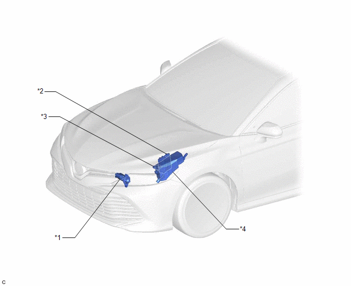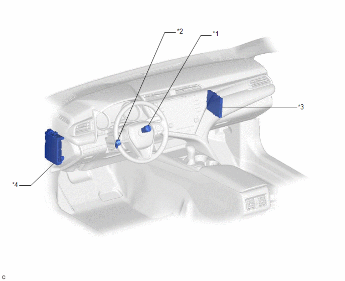

Emplacement Des Pieces Constitutives
EMPLACEMENT DES PIECES CONSTITUTIVES
SCHEMA

|
*1 | ENSEMBLE DE DEMARREUR |
*2 | ECM |
|
*3 | ENSEMBLE DE CONTACTEUR DE POSITION DE STATIONNEMENT/POINT MORT |
*4 | ENSEMBLE DE BLOC DE RELAIS DE COMPARTIMENT MOTEUR ET DE BLOC DE JONCTION - RELAIS ST - FUSIBLE ST N° 1 - FUSIBLE FL MAIN - FUSIBLE J/B-B (sans système de clé intelligente) |
SCHEMA

|
*1 | CONTACTEUR DU MOTEUR (avec système de clé intelligente) |
*2 | ENSEMBLE DE CONTACTEUR D'ALLUMAGE OU DE DEMARREUR (sans système de clé intelligente) |
|
*3 | ECU DE CERTIFICATION (ENSEMBLE D'ECU DE CLE INTELLIGENTE) (avec système de clé intelligente) |
*4 | ENSEMBLE DE BLOC DE JONCTION DE TABLEAU DE BORD - FUSIBLE AM2 (sans système de clé intelligente) |
Schema Du Systeme
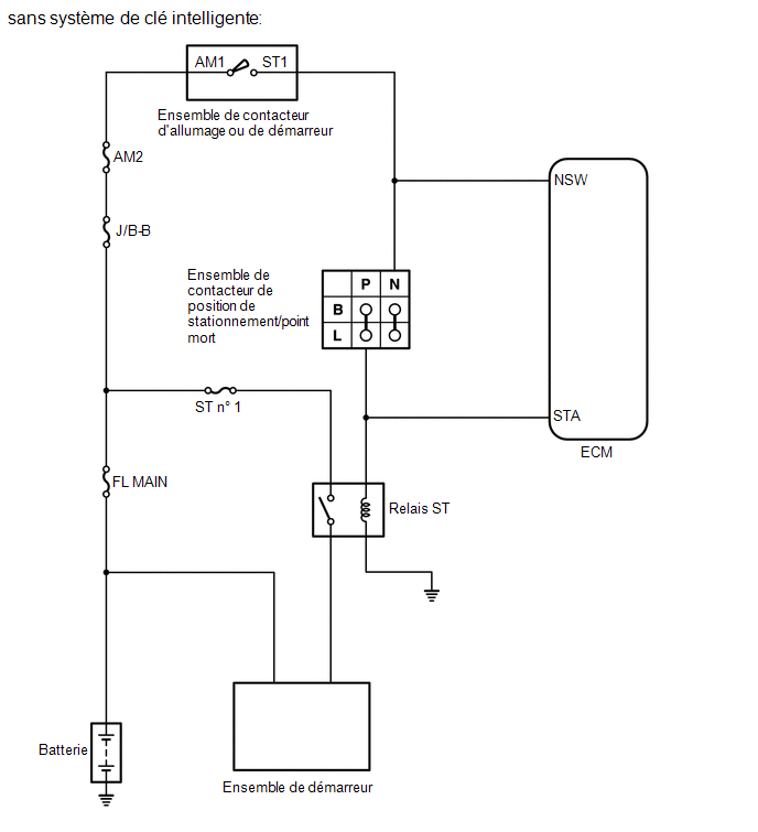
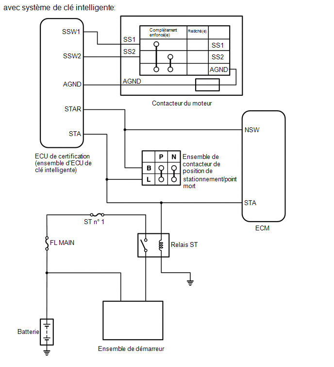
SCHEMA DU SYSTEME


 Relais
Capteur De Vitesse Arriere
Pieces ConstitutivesPIECES CONSTITUTIVES SCHEMA
*A sans système de frein de stationnement électrique
- -
*1 BOUCHON D'ORIFICE DE REGLAGE DE MACHOIRE DE FREIN DE STATIONNEMENT
*2 ENSEMBLE DE MOYEU D'ESSIEU ET DE ROULEMENT ARRIERE
*3 DISQUE ARRIERE
...
Remontage
REMONTAGE MESURE DE PRECAUTION / REMARQUE / CONSEIL
CONSEIL:
Procéder de la même façon pour le côté droit et pour le côté gauche.
La procédure suivante se rapporte au côté gauche.
PROCEDURE 1. REPOSER LE CORPS ET LA LENTILLE DE FEU ARRIERE (fabrication TMC)
2. REPOSER LA G ...
Verification
VERIFICATION PROCEDURE 1.
VERIFIER L'ENSEMBLE DE THERMISTANCE
(a) Mesurer la résistance en fonction de la (des) valeur(s)
indiquée(s) dans le tableau ci-dessous. Résistance standard:
Branchement du tester
Condition Condition
spécifiée
1 - 2 10°C
(50° ...